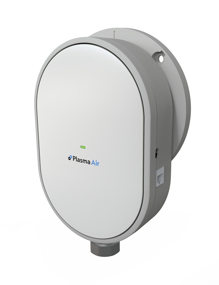
INSTALLATION, OPERATION & MAINTENANCE MANUAL
Plasma Air RapidPURE
Notice: This product is to be used only as directed. Read entire manual before installation. Do not use the device unless it is properly installed.
Click here for the RapidPURE manual in PDF format.
OVERVIEW
The PlasmaAir RapidPURE is a duct mounted, self-cleaning, maintenance-free needlepoint ionizer that produces positive and negative ions that neutralize harmful pollutants, odors and pathogens (mold spores, bacteria and viruses). This compact self-cleaning unit automatically removes dust and dirt build-up on the needles eliminating the need for maintenance.
The unit is typically installed in supply ducts utilizing the pre-drilled flange and factory applied gaskets. Multiple units can be daisy chained into a single alarm contact.
The RapidPURE 120-240V accepts supply voltages from 120V to 240V AC.
The RapidPURE 12-24V accepts supply voltages from 12V to 24V AC or DC.
Both models are UL 2998 validated for zero ozone emissions.
WHAT IS INCLUDED
Included with the PlasmaAir RapidPURE kit are the following components:
a. Mounting Plate x 1.
b. Chassis x 1.
c. Front Cover x 1.
d. Self-tapping screws x 4.
SAFETY PRECAUTIONS
• Installation should be performed by a qualified professional.
• Use appropriate personal protective equipment (PPE) such as gloves and safety glasses.
MECHANICAL INSTALLATION INSTRUCTIONS
*WARNING*
• Please ensure that the power to the HVAC system is turned off.
• Follow all local and national electrical and building codes.
• Do not connect to power before mechanical installation is complete.
*CAUTION*
• This product is suitable for mounting into duct of metallic construction only. Installation must be such that the structural integrity of the ducting is not compromised.
• Mount units to allow access to the ionization unit power switch and connections. This product shall not be installed behind a suspended floor/ceiling or a structural wall, ceiling, or floor.
• This model should not be mounted in a location where the air temperature exceeds 131° F (55°C). This usually means that it should not be installed at the outlet of a gas or oil-fired furnace.
LOCATION
The preferred location for mounting is in the supply air duct as close to the treated space as possible. Be sure to pick a location before any branch duct take-offs. Install in a straight section of duct work a minimum of 3 feet (1m) from any duct transitions.
INSTALLATION STEPS
To mount the unit into a duct, follow the steps below,
a. Ensure the power to the HVAC system has been turned off.
b. Mounting the RapidPURE on the duct requires a 5” hole. Please ensure the centre of the 5” hole is centrally positioned vertically on the duct wall to enable the ionization device to be optimally positioned within the airflow duct airflow (Figure 1).
c. When the location of the hole has been determined and marked, then cut out the 5-inch diameter hole in the duct using a 5” Hole-Saw (Figure 1).
d. Align the wave arrows on the mounting ring with the ducting airflow direction (Figure 2).
e. Insert the round mounting plate into the duct opening so that the flange’s gasket is in contact with the outside of the duct (Figure 3).
f. Hold in place and secure the mounting plate to the duct with the 4 self-tapping screws (Figure 3).
g. Connect the power cables to the terminal, exposed at front of the main chassis. (Please refer to the electrical installation instructions in the next section.)
h. After connecting all wires, secure the main chassis to the mounting plate using a snap fit (Figure 4).
i. Once you are content that the main chassis is in place then install the front cover (snap fit) (Figure 5). Make sure to align the wave arrows on the mounting ring with the wave arrows on the main chassis.
j. (Optional) Multiple units can be daisy chained together by means of RJ-45 cabling (Figure 6).
k. Once the unit is in place then the power to HVAC system and device can be turned on.
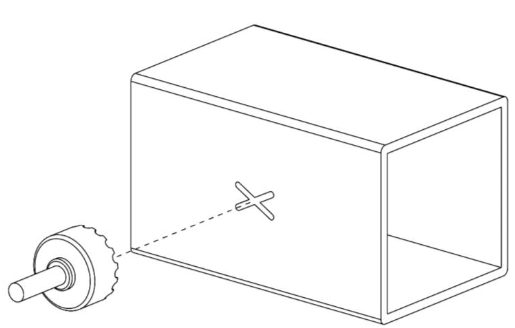
Figure 1: Mounting the RapidPURE on the duct requires a 5” hole. Please ensure the centre of the 5” hole is centrally positioned vertically on the duct wall to enable the ionization device to be optimally positioned within the airflow duct airflow. When the location of the hole has been determined and marked, then cut out the 5-inch diameter hole in the duct using a 5” Hole-Saw.
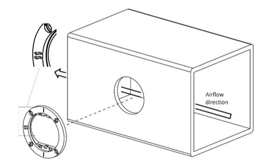
Figure 2: Align the wave arrows on the mounting ring with the airflow direction in the ducting.
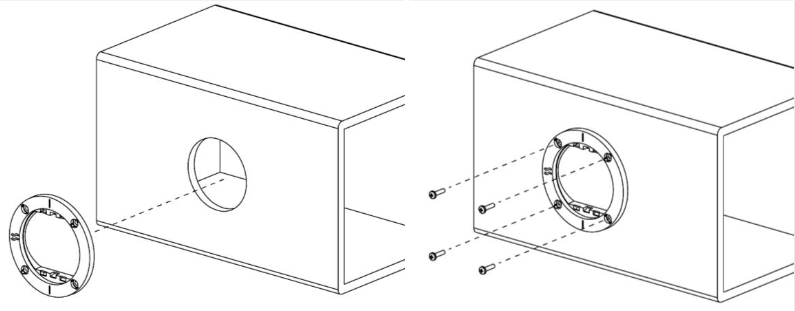
Figure 3: Insert the round mounting plate into the duct opening so that the flange’s gasket is in contact with the outside of the duct. Hold in place and secure the mounting plate to the duct with the 4 self tapping screws.
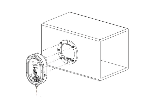
Figure 4: After connecting all wires, secure the main chassis to the mounting plate using a snap fit. Make sure to align the wave arrows on the mounting ring with the wave arrows on the main chassis.
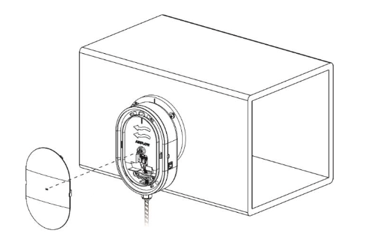
Figure 5: Once you are content that the main chassis is in place then install the front cover (snap fit).
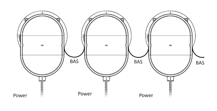
Figure 6: (Optional) multiple units can be daisy chained together by means of RJ-45 cabling.
REMOVING THE FRONT COVER AND UNMOUNTING FROM A DUCT
To unmount the unit from a duct, follow the steps below,
a. Ensure the power to the HVAC system has been turned off.
b. Remove the front cover by inserting a flat screwdriver into either side of the RapidPURE chassis, push and pivot as illustrated in Figure 7.
c. With the front cover removed, insert the flat screwdriver into the slot on the top of the RapidPURE chassis, pivot up and pull the chassis out of the mounting ring (Figure 8).
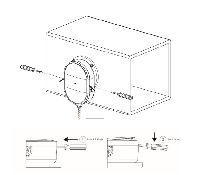
Figure 7: Remove the front cover on the RapidPURE by inserting a tool on either side, pushing and pivoting as shown.
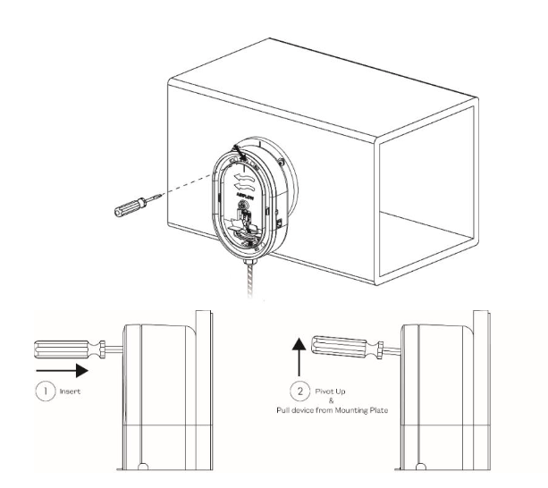
Figure 8: Unmount the RapidPURE by inserting a tool in the slot at the top of the chassis, pivoting up and pulling the chassis out of the mounting ring.
ELECTRICAL INSTALLATION INSTRUCTIONS
*WARNING*
• Do not connect to power before installation is complete.
• Always disconnect power to the unit before handling the ionizer.
• Use an insulated 3-core power cord (Figure 9).
1. All field wiring to be in accordance with the National Electric Code Section 725 and authorities having jurisdiction.
2. It is recommended that surge protection be installed with this ionizer at the equipment level, building level, or circuit breaker panel feeding the product.
3. If a step-down transformer is used to feed the ionizer, the transformer must be grounded.
4. Do not install the ionizer on the same circuit as a UV Lamp or connect to the same transformer as a UV Lamp.
5. The appropriate flexible conduit and fittings may be required and fitted accordingly for the specific application. Note: NOT intended to be connected to RIGID metal conduit.
6. Connect appropriate power to ionizer:
RapidPURE 120-240V (Figure 10)
o Connect mains Live and Neutral to terminals marked L and N respectively on the lever-operated power connector.
o Connect Earth to the terminal marked ![]() on the lever-operated power connector.
on the lever-operated power connector.
RapidPURE 12-24V (Figure 11)
o Connect power to terminals marked IN and IN on the lever-operated power connector. (Polarity does not matter.)
o Connect Earth to the terminal marked ![]() on the lever-operated power connector.
on the lever-operated power connector.
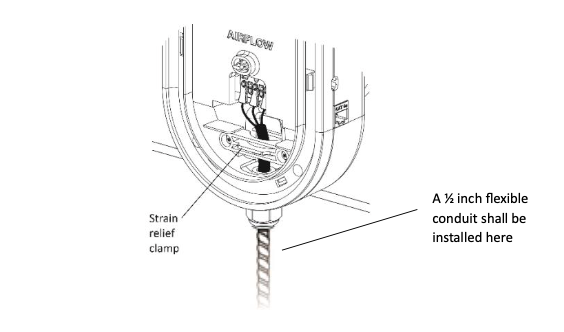
Figure 9: The ½ inch flexible conduit shall be installed. The insulation shall not be removed until after the strain relief clamp identified in this illustration.
Note: NOT intended to be connected to RIGID metal conduit
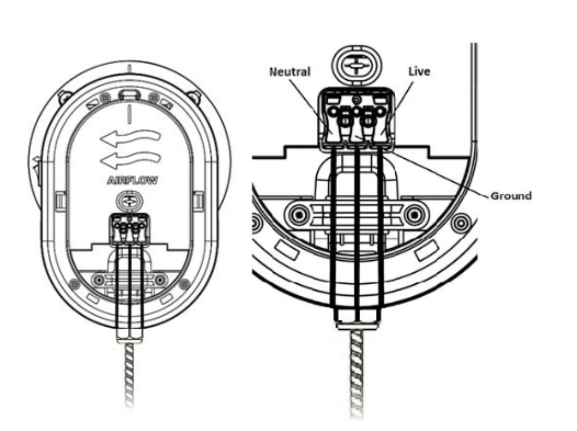
Figure 10: RapidPURE 120-240V electrical wiring. Connect mains Live and Neutral to terminals marked L and N respectively on the lever-operated power connector. Connect Earth ![]() operated power connector.
operated power connector.
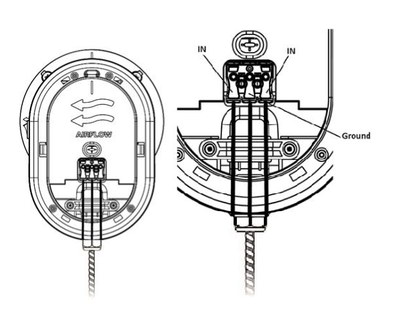
Figure 11: RapidPURE 12-24V electrical wiring. Connect power to terminals marked IN and IN on the lever- operated power connector. (Polarity does not matter.) Connect Earth ![]() operated power connector to the terminal marked on the lever-operated power connector.
operated power connector to the terminal marked on the lever-operated power connector.
WARNING
Connecting the incorrect supply (i.e. mains) to the RapidPURE 12-24V device will destroy it immediately.
Connect power wires to the power inlet connector by pressing firmly on the relevant lever, inserting the appropriate wire, then releasing the lever. Repeat as necessary for the other wires. Strip wire insulation as necessary.
OPTIONAL: Building Automation Systems (BAS) INTERFACE INSTALLATIONS
The RapidPURE features a pair of dry contacts which, when closed, signify that the ionizer is powered and working correctly. This can easily be interfaced to various BAS systems. (wiring and BAS controller by others):
1. Dry Contacts
Dry Contact #1 is internally connected to RJ45 J1 Pin 1.
Dry Contact #2 is internally connected to RJ45 J2 Pin1.
J1 Pin 2 is internally connected to J2 Pin 2.
See Figure 12.
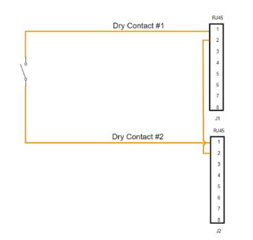
Figure 12: Dry Contact Internal Schematic
2. Two RJ45 Connectors are provided to allow convenient daisy-chaining of multiple units using off-the shelf RJ45 Twisted Pair cables. The BAS should be configured to monitor a closed contact.
3. If there is only one unit in the chain to be monitored, the unit is wired to the BAS as in Figure 13.
4. If there are multiple units in a chain to be monitored, the units are wired to the BAS as in Figure 14.
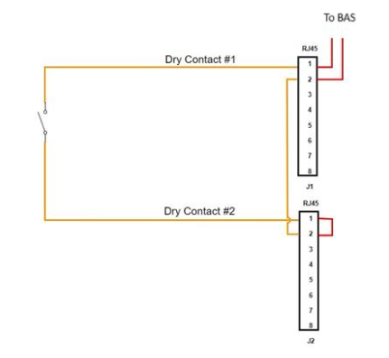
Figure 13: Dry contact external wiring - single unit, no chaining.
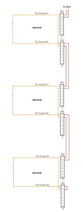
Figure 14: Dry contact external wiring - multiple units with chaining.
SELF-CLEANING & NO MAINTENANCE
Device is self-cleaning and requires no maintenance.
TROUBLESHOOTING
If the unit is not operating, check the following:
1. Verify that all power connections are correct and tight. Reconnect any loose wires as necessary.
2. Verify that the supply fan is running to initiate operation, and that the LED illuminates.
Otherwise, contact Plasma Air for further support.

