Quick Start Guide
Published
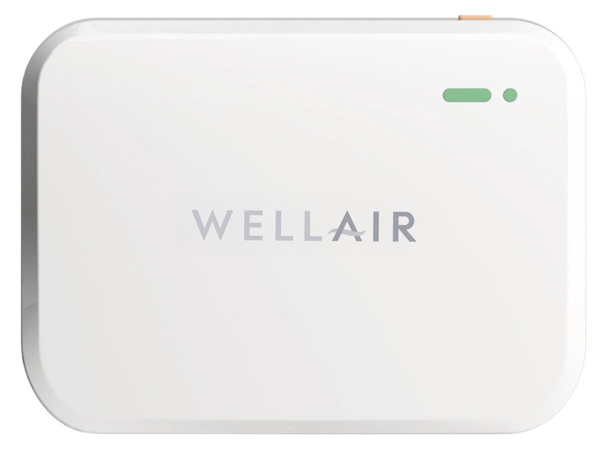
NanoDetect Quick Start Guide
GET STARTED
This QuickStart guide aims to help you with the initial setup of your NanoDetect, where it’s connected to NanoView. For local only installations, reference the Resources section, where you can find setup instructions for all different installation types.
NanoDetect PRO (Wi-Fi): SKU 100080
NanoDetect PRO-S (Cellular): SKU 100081
PHASE 1: DIGITAL PREP
App Download
Download the NanoView App to begin setting up. This is required for local and networked setups.
The WellAir NanoView App can be downloaded from Google or Apple app store.


Dashboard Access
To access the NanoView Dashboard, navigate to the following link and log in using your assigned credentials: https://cloud.wellairsolutions.com/#/login
PHASE 2: HARDWARE SETUP
WHAT'S IN THE BOX
Each NanoDetect PRO or PRO-S package contains the following components:
1. (1) NanoDetect PRO device
2. (2) mounting brackets
3. (2) Screws
4. (1) sensor capsule
5. (1) USB cable and US adaptor plug
6. (1) Installation manual
SAFETY PRECAUTIONS
Failure to adhere to these instructions may result in device malfunction or damage.
• Do not disassemble or modify the device
• Keep the device away from open flames, heat, cold, and liquid sources.
• This device is not intended as a reference monitor; WellAir/Plasma Air will not be liable for any damage caused by inaccurate readings.
• Avoid shocks or impacts to the device.
**WARNING: Do not connect to power before installation is complete.**
HARDWARE OVERVIEW
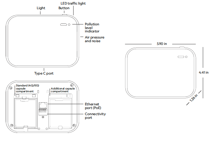
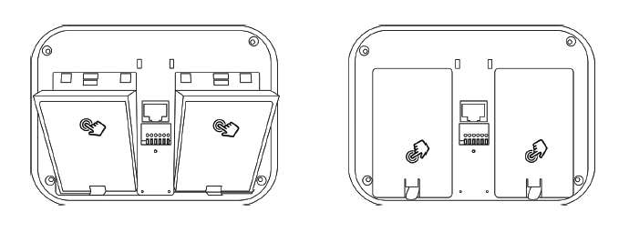
CAPSULE INSTALLATION:
Step 1 Pop off the capsule cover. Please note that a flat screwdriver may be needed if the capsule covers are tight.
Step 2 Insert the sensor at a 30-degree angle into the designated slot. Once aligned, press down on the top side of the capsule to secure it in place.
Step 3 Position the cover over the capsules and press down firmly on the upper part to ensure a secure fit.
MOUNTING
Mount the NanoDetect PRO device to wall in line with customer or building scheme requirements which are typically:
• 3.6 ft to 5.6 ft (1.1m to 1.7m) above the floor
• Clear of doors, windows and air vents
• Close to a power source
Mounting processes include:
1. DRY WALL
a. Attach the small bracket to the device with screws
b. Mount bracket A on the wall
c. Slide the device onto bracket A for secure placement
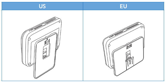
2. ELECTRICAL BOX MOUNT – REGIONAL VARIATIONS
a. Line up the plate with your in-wall electrical box and mount it in place using Electrical Box Screws (vertical for US and horizontal for EU as per dry wall mount).
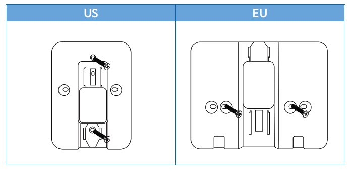
b. Slide the device into the wall-mounted brackets until securely positioned.
WARNING
• Please ensure that the power to the electrical box is turned off.
• Follow all local and national electrical and building codes.
• Do not connect to power before mechanical installation is complete.
PHASE 3: POWER & CONNECTIVITY
POWER SUPPLY OPTIONS
The Sensor supports multiple power options for flexible installation:
• Type C (cable and adaptor/plug included)
• 24V AC
• 10-30V DC
• PoE (Power over Ethernet)
Connect the necessary power and connectivity cables:
Power Cable
• Connect 10-30V DC or 24V AC to the +/- terminals on the connectivity port.
• For Power over Ethernet (PoE), connect to the Ethernet port
Connectivity Cables
• Connect Modbus or BACnet cables to the A/B terminals on the connectivity port.
• Connect the Ethernet cable to the Ethernet port.
DEVICE WI-FI ONBOARDING
Before You Begin:
• Ensure the NanoView App is installed on your mobile device
• Ensure Bluetooth is enabled on your mobile device and permissions are granted to the NanoView App
• Ensure your mobile device is connected to the same Wi-Fi network you want the sensor to use
• Have your Wi-Fi network name (SSID) and password available
|
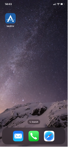
1. Open the NanoView App on your mobile device. 2. Create or log in to your account. If this is your first time using the app, follow prompts to create a username and password. Returning users can log in with existing credentials. 3. Enable Bluetooth access Confirm that Bluetooth is turned on and shared with the NanoView App when prompted. |
 |
|
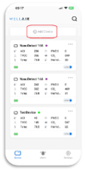
4. Start the Add Device process |
 |
|
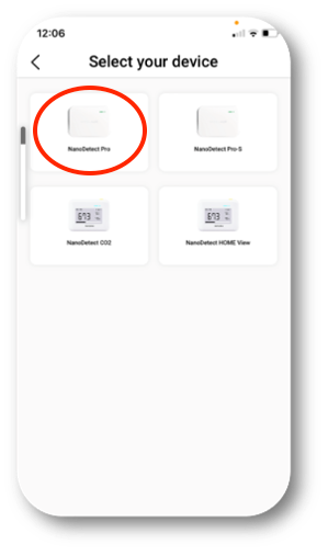
5. Select the device type On the next screen, select NanoDetect PRO
|
 |
|
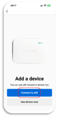
6. Choose Wi-Fi setup Select the option to add the device using a Wi-Fi network. |
 |
|
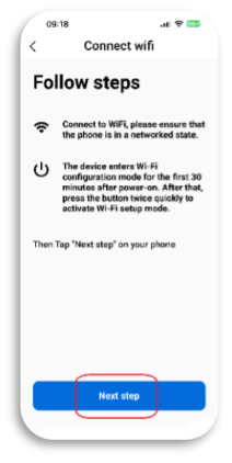
7. Review Wi-Fi and device status The app will display your current Wi-Fi connection and device status. When ready, tap Next Step. |
 |
|
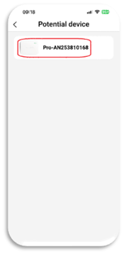
8. Select your sensor A list of available sensors will appear. Identify your sensor by matching: -Device model (e.g. NanoDetect PRO) -Serial number (located on the product label on the back of the sensor) Select the correct device from the list. |
 |
|
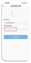
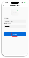
9. Enter Wi-Fi credentials Confirm the Wi-Fi network name (SSID), enter the network password, and tap Connect. 10. Confirm successful connection Once the setup is complete, the sensor will appear on the main Devices screen, indicating it is successfully connected to the Wi-Fi network. |
  |
TROUBLESHOOTING
The troubleshooting guide can be access using the link: https://www.wellairsolutions.com/news/troubleshooting
RESOURCES
For more information, guides and resources, please visit our dedicated support portal: https://www.wellairsolutions.com/support-center-nanodetect-pro
DECLARATION of CONFORMITY
The NanoDetect PRO series meets essential requirements for CE, FCC, RoHS, and REACH certifications.
FCC ID XMR2023FCM362K
This device complies with part 15 of the FCC Rules. Operation is subject to the following two conditions:
(1) This device may not cause harmful interference, and
2) This device must accept any interference received, including interference that may cause undesired operation.
BACK TO SUPPORT CENTER